Replacement & Repair Parts
Washing Machine Door Handle Reconstruction
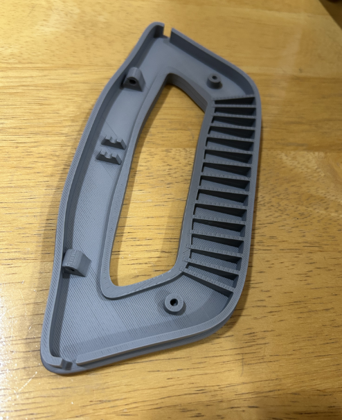
Rebuilding a functional part from geometry and interfaces
This project is a reverse-engineering practice case based on a real type of broken appliance handle. The goal is not to copy an existing STL. Instead, the part is reconstructed from reference images and a set of assumed measured dimensions, following the same workflow that would be used with a physical broken part in hand.
Problem & Constraints
A replacement handle is not just an exterior shape. The interfaces inside the part determine whether it can work.
Functional constraints
- Reconstruct the outer handle shape and hand opening.
- Locate the long metal pivot/rod in 3D space.
- Keep support holes coaxial with the rod.
- Provide clearance for latch and spring-related geometry.
- Add locating bosses and shallow edge recesses seen in the reference structure.
Reverse-engineering constraints
- Overall shape can be recovered from photographs or a scan.
- Critical axes, hole diameters, and interfaces should come from physical measurements when a real part is available.
- For this practice case, missing measurements are replaced with reasonable engineering assumptions.
- The metal rods/pins are modeled as reference bodies but are not part of the printed MainBody.
Design Development
The model was built from the outside inward, moving from visual geometry to the interfaces that control function.
MainBody geometry
- Outer perimeter reconstructed from a calibrated reference image.
- Hand opening traced and adjusted as a separate closed profile.
- Base thickness and rounded outer edges established first.
- Inner and outer raised walls added on the structural side.
- Repeated reinforcing ribs created along the lower region.
Functional geometry
- Metal rod represented by an independent solid reference body.
- Support bosses use a clearance hole around the rod.
- Support roots are blended into the MainBody with fillets to reduce sharp stress concentrations.
- A center pivot and latch space were modeled to understand the internal mechanism.
- Two locating bosses and paired shallow recesses complete the major visible interface features.
Design Knowledge Gained
Each JeffForge case is used to build reusable engineering knowledge, not just a single CAD file.
Connection & Pivot Geometry
Modeling a suspended axis, coaxial supports, clearance holes, and metal reference parts separately from the printed plastic body.
Ribs & Load Paths
Using thin ribs to reinforce a wide molded-style shell and recognizing when patterned rib length must change as inner and outer curves diverge.
Measurement Strategy
Separating visual shape capture from critical interface measurement: photos or photogrammetry for form, calipers and reference axes for functional dimensions.
Failure-Aware Redesign
Identifying likely high-stress regions around supports and pivots, then using wall thickness, root geometry, and fillets to create a more printable replacement.
Need a replacement part designed?
JeffForge focuses on low-consequence functional parts where the original geometry, interfaces, and use conditions can be understood and verified.
Contact JeffForge